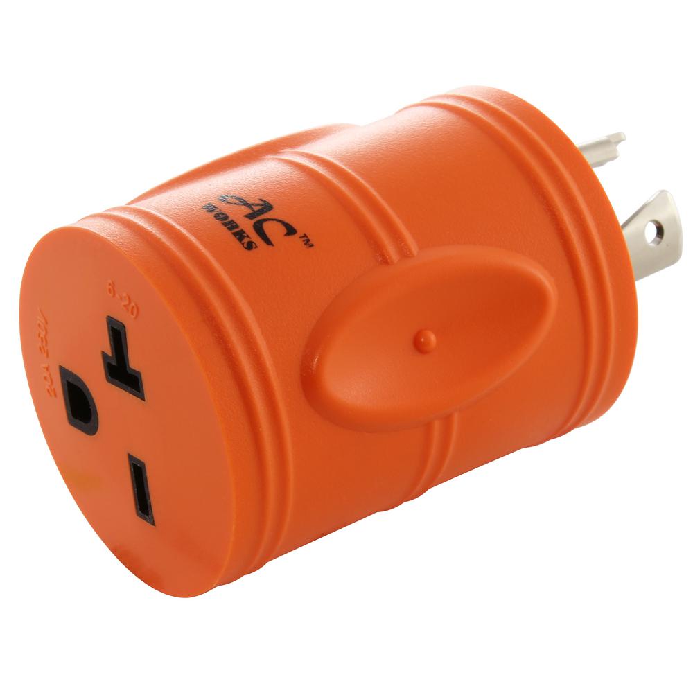
L6 20 Connector Diagram
View L6 20 Connector Diagram Background. Nema connectors are power plugs and receptacles used for ac mains electricity in north america and other countries that use the standards set by the us national electrical manufacturers association. Connector diagram connector diagram j8 j9 j4 j7 j11 j10 j301 ps board scanner unit only l200/l201 cis module.

The gx series connectors mainly seen around aviation, usually smaller and fewer pin (i see mention of gx16, gx20, gx12, the number is the barrel diameter in mm).
Refer to the appropriate pinout diagram for the the ulink2 provides five jtag connectors that support the various cable types needed for debugging different targets: Note 1) the input signals (di4~di8, output signals (do1~do4) are the factory default signals. L298n (multiwatt vert.) tab connected to pin 8. Figure 1 figure 1 figure 2 figure 2 figure 3 figure 3 figure 1 figure 1 figure 2 figure 2 figure 3 figure 3.
Belum ada Komentar untuk "L6 20 Connector Diagram"
Posting Komentar